Use the I2C Signal type to decode two channels using the full I2C serial protocol.
Signal Name
Change the text displayed here to help you identify this signal definition. If the name has already been used, it will automatically be appended with a numerical value in brackets (i.e. [2]). The name displayed here will be used in the Waveform Views, Searches, Tabular Views, Exports, Trigger Configurations and all menu references.
Disable Signal
Check this item to completely disable the Signal Definition. It is recommended to disable any signals that use channels that are not connected to a physical device. When a capture takes place ("Run"), any channels that are assigned to disabled signals will be ignored instead of using valuable capture space.
Plot Output
Check this item to enable Plotting for this signal. If checked, all waveform views will display plotted data as defined by the Plot Series configurations. You must enable and configure at least one Plot Series before any plotted data is visible. Up to 4 individual plots can be configured for each signal. (see: Plotting Signal Data).
Color Selection & Examples
An example of the signal is displayed in the current color scheme, followed by an example of the current color selections for this signal and a color reset button. Clicking on one of the color squares will open the Color Selection dialog to change the Signal line color and its background color if a color other than the theme color is desired.
Reset Signal Colors
This button will reset the colors for this signal so that they will match the currently selected color theme (see: Color Themes).
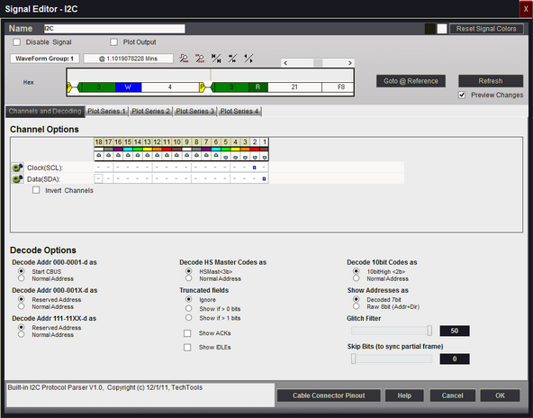
Channel Options
This is where you will associate a signal definition with the physical channels or connections to the outside world. Each signal definition type will have one or more channel selection groups and will allow one or more channels to be selected for each group. Each channel selection group will be identified on its left if more than one group is available for the signal type.
To select a channel, click on the " - " below the proper color (and channel number) that corresponds to the physical connection of the DigiView Cable (see: Connecting the Data Lines). Channels that are selected for this signal will replace the " - " with a blue square as shown above. The gray arrow beneath each channel color is an activity indicator that displays the activity of the channel as compared to the activity of all the other channels (relational, not real time).
Clock (SCL) Channel Selection
Selects which physical channel to assign to the CLOCK.
Invert Channels
If selected, the captured data for SCL will be inverted before decoding and displaying (only affects this Signal Definition).
Data (SDA) Channel Selection
Selects which physical channel to assign to the DATA bus.
Invert Channels
If selected, the captured data for SDA will be inverted before decoding and displaying (only affects this Signal Definition).
Glitch Filter
Selects the amount of noise filtering. Should be set to 50ns for low speed buses and reduces for FAST buses.
Skip Bits (to sync partial frame)
Specifies how many bits to ignore at the start of the buffer. Useful for syncing up when capture starts mid-frame.
Decode Addr 000-0001-d as
Selects between the standard I2C decoding for this address range or decoding it as normal 7 bit devices.
Decode Addr 000-001X-d as
Selects between the standard I2C decoding for this address range or decoding it as normal 7 bit devices.
Decode Addr 111-11XX-d as
Selects between the standard I2C decoding for this address range or decoding it as normal 7 bit devices.
Decode HS Master Codes as
Selects between the standard I2C decoding for this address range or decoding it as normal 7 bit devices.
Decode 10bit Codes as
Selects between the standard I2C decoding for this address range or decoding it as normal 7 bit devices.
Truncated fields
Specified whether to show truncated/partial fields or not. 1 bit truncated fields common and unavoidable so the options include showing only if > 1 bit.
Show ACKs
Selects whether to show ACKs in the waveforms, tables and searches NAKs are always shown.
Show Addresses as
The I2C spec defines 7 bit addresses and a 1 bit direction (R/W) in teh first field. Sometimes it is convenient to think of this as a single 8 bit value. This option specifies whether to show as 2 fields (per spec.) or as a single 8 bit field.
Show IDLEs
Specifies whether idle time between fields should be shown as a hashed field or if the current field should just extend to the next field.
Plot Series 1 - 4
If "Plot Output" is selected, up to 4 plots can be defined. If enabled and at least one Plot Series is defined, all waveform views will display the data in a plotted format. (see: Plotting Signal Data).
Display Fields
Start
Field type used to show start and repeated start event.
Shows ' S ' for start or ' Sr ' for repeated start.
Stop
Field type used for stop events. Shows ' P '.
Addr
Field type used for normal 7bit address fields
Addr8
Field type used to show first byte as 8 bit address+direction
Data
Field type used for most characters. Shows the received byte
Ack
Field type used to show Acknoledge bit. Shows ' A '
Nak
Field type used to show Nak bits. Shows ' N '.
WRITE
Field type used to show WRITE bits. Shows ' W '.
READ
Field type used to show READ bits. Shows ' R '.
General-Call
Field type used to show first byte code is General-Call.
Shows ' Gen-Call '
Start-Byte
Field type used whenthe first byte code is START BYTE.
Shows ' START '.
HS Master
Field type used when first byte code is High Speed Master.
Shows ' HS Master: ' followd by the 3 bit master ID
CBUS
Field type used when the first byte code is CBUS.
Prints the word CBUS.
Reserved
Field type used when the first byte is a reserved address.
Prints the word 'RESERVED: ' followed by the actual data
10bitMode
Field type used when the first byte code is 10 bit Mode.
Prints ' 10bitMode: ' followed by the high 2 bits of the 10bit address.
Truncated
Field type used when a byte is truncated (bt a stop or repeated start)
Prints ' T: ' followed by the received data.