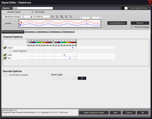
Use the I2S Signal type to decode three channels using the Inter-IC Sound bus protocol. The example below has been configured for Plotting (see: Plotting Signal Data).
Signal Name
Change the text displayed here to help you identify this signal definition. If the name has already been used, it will automatically be appended with a numerical value in brackets (i.e. [2]). The name displayed here will be used in the Waveform Views, Searches, Tabular Views, Exports, Trigger Configurations and all menu references.
Disable Signal
Check this item to completely disable the Signal Definition. It is recommended to disable any signals that use channels that are not connected to a physical device. When a capture takes place ("Run"), any channels that are assigned to disabled signals will be ignored instead of using valuable capture space.
Plot Output
Check this item to enable Plotting for this signal. If checked, all waveform views will display plotted data as defined by the Plot Series configurations. You must enable and configure at least one Plot Series before any plotted data is visible. Up to 4 individual plots can be configured for each signal. (see: Plotting Signal Data).
Color Selection & Examples
An example of the signal is displayed in the current color scheme, followed by an example of the current color selections for this signal and a color reset button. Clicking on one of the color squares will open the Color Selection dialog to change the Signal line color and its background color if a color other than the theme color is desired.
Reset Signal Colors
This button will reset the colors for this signal so that they will match the currently selected color theme (see: Color Themes).
Channel Options
This is where you will associate a signal definition with the physical channels or connections to the outside world. Each signal definition type will have one or more channel selection groups and will allow one or more channels to be selected for each group. Each channel selection group will be identified on its left if more than one group is available for the signal type.
To select a channel, click on the " - " below the proper color (and channel number) that corresponds to the physical connection of the DigiView Cable (see: Connecting the Data Lines). Channels that are selected for this signal will replace the " - " with a blue square as shown above. The gray arrow beneath each channel color is an activity indicator that displays the activity of the channel as compared to the activity of all the other channels (relational, not real time).
Clock Channel Selection
Selects which physical channel to assign to the CLOCK.
Invert Channels
If selected, the captured data for CLOCK will be inverted before decoding and displaying (only affects this Signal Definition).
Data Channel Selection
Selects which physical channel to assign to DATA.
Invert Channels
If selected, the captured data for DATA will be inverted before decoding and displaying (only affects this Signal Definition).
WS Channel Selection
Selects the physical channel to use as the Word Select (WS). The word select determines whether the data is for the Left or Right audio channel.
Invert Channels
If selected, the captured data for WS will be inverted before decoding and displaying (only affects this Signal Definition).
Convert Data to Unsigned
When selected, the data word will be converted from a signed value to an unsigned value before displaying or plotting.
Word Length
Specifies how many bits to use for the data word. Selection range is from 4 to 32 bits.
Plot Series 1 - 4
If "Plot Output" is selected, up to 4 plots can be defined. If enabled and at least one Plot Series is defined, all waveform views will display the data in a plotted format. (see: Plotting Signal Data).